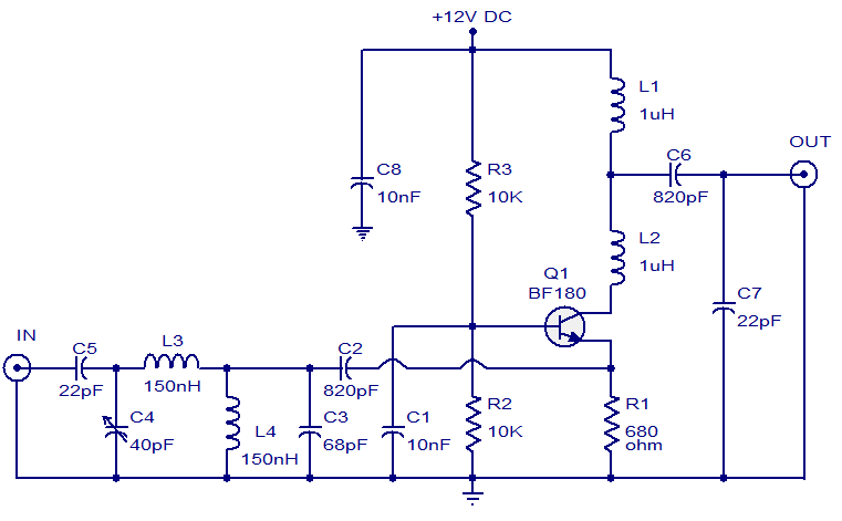
- The circuit shown here is of a TV antenna booster based on the transistor BF180. The circuit operates in the UHF band and has a gain of 15dB.
- Capacitors C2,C3 C4 ,C5 and inductors L3, L4 forms a UHF band pass filter. The input signal is fed to the emitter of Q1 through this filter.
- Resistor R2 and R3 biases the transistor Q1 which is wired in the common base configuration.
NOTES:
- Assemble the circuit on a good quality PCB.
- For better performance, enclose the circuit in a metal box.
- The circuit can be powered from 12V DC.
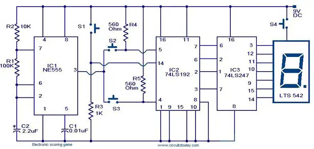
- A simple scoring game circuit that can be used for all occasions when a dice is needed.The circuit is based on a NE555 timer,a 74LS192 counter,a74LS247 decoder and a & segment LED display.
- The timer IC1 will produce the clock for the counter IC(IC2) whose frequency is determined by R1 and C2.When S2 is pressed the IC2 will count in up mode and when S3 is pressed the IC2 will count in down mode.The IC 3 will decode the count to display it on the seven segment LED display .Thats about the working of the circuit.The circuit is designed strictly sticking on to the basics of counters and is a good one for beginners.
NOTES:
- To play the game switch the power ON and press S1 to reset the counter.
- Now press S2 or S3 and release .The IC2 will hold the last count .Now press S4 to see the score on display.That’s your score.Now the second person can try.
- Each time one tries, he should press the S1 to reset the count and then press S2 or S3 and then S4 to see the score.
- Circuit can be powered from a 9V radio cell or a 9V regulated DC power supply .