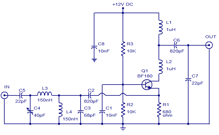
- The circuit shown here is of a TV antenna booster based on the transistor BF180. The circuit operates in the UHF band and has a gain of 15dB.
- Capacitors C2,C3 C4 ,C5 and inductors L3, L4 forms a UHF band pass filter. The input signal is fed to the emitter of Q1 through this filter.
- Resistor R2 and R3 biases the transistor Q1 which is wired in the common base configuration.
NOTES:
- Assemble the circuit on a good quality PCB.
- For better performance, enclose the circuit in a metal box.
- The circuit can be powered from 12V DC.