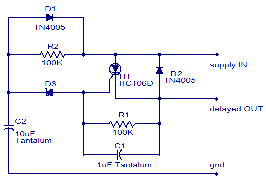
- The circuit diagram shown here is of a simple DC power delay circuit that is based on an SCR.
- This circuit is a very handy one and can be employed in many applications.
- When the input power is applied the capacitor C2 charges through resistor R2 and when the voltage across the capacitor just exceeds the Zener diode D3’s breakdown voltage, it breaks down and the SCR H1 is triggered and the delayed power will be available at the delayed OUT terminal.
NOTES:
- The circuit must be assembled on a good quality PCB.
- The Zener diode must be rated half the input supply voltage.
- The current capacity of the circuit depends on the SCR and here it is 4A.
- The circuit diagram shown here is of 12V DC fan speed controller using the IC LM2941CT which is a low drop out 1A voltage regulator.
- The IC has a dropout voltage as low as 0.5 and has also many useful features like power supply reverse protection, thermal protection, short circuit protection etc. The maximum output current the IC can source is 1A.
- The 12V DC supply is connected between the Vin (pin4) and ground (pin3) of the IC.
- The load, which is the fan, is connected across the Vout (pin5) and ground (pin3) of the IC. The network comprising of potentiometers R1, R2 and resistor determines adjust current (Iadj) of the IC.
- By varying the Iadj using the POT R2 we can adjust the output voltage of the IC and hence the fan speed.
NOTES:
- The circuit can be powered from 12V DC.
- The maximum possible load current is 1A.
- A heat sink is recommended for the IC.
- POT R1 can be used to adjust the minimum fan speed.
- POT R2 can be used to adjust the fan speed.

- Here is a simple fire alarm circuit based on a LDR and lamp pair for sensing the fire.The alarm works by sensing the smoke produced during fire.The circuit produces an audible alarm when the fire breaks out with smoke.
- When there is no smoke the light from the bulb will be directly falling on the LDR.The LDR resistance will be low and so the voltage across it (below .6V).The transistor will be OFF and nothing happens.
- When there is sufficient smoke to mask the light from falling on LDR, the LDR resistance increases and so do the voltage across it.Now the transistor will switch to ON.
- This gives power to the IC1 and it outputs 5V.This powers the tone generator IC UM66 (IC2) to play a music.This music will be amplified by IC3 (TDA 2002) to drive the speaker.
- Resistor R6 is meant for protecting the transistor when R4 is turned towards low resistance values .Resistor R2 and R1 forms a feedback network for the TDA2002 and C1 couples the feed back signal from the junction of R1 & R2 to the inverting input of the same IC.
- The diode D1 and D2 in combination drops 1.4 V to give the rated voltage (3.5V ) to UM66 .UM 66 cannot withstand more than 4V.
NOTES:
- The speaker can be a 32Ω tweeter.
- POT R4 can be used to adjust the sensitivity of the alarm.
- POT R3 can be used for varying the volume of the alarm.
- Any general purpose NPN transistor(like BC548,BC148,2N222) can be used for Q1.
- The circuit can be powered from a 9V battery or a 9V DC power supply.
- Instead of bulb you can use a bright LED with a 1K resistor series to it.