AUTOMOBILE TURN SIGNAL CIRCUIT
- This is a simple circuit that can be used as a sequencial signal light in automobiles.
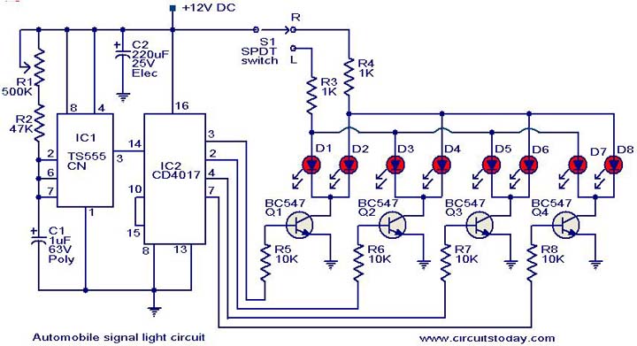
- The circuit is based on two ICs. A TS 555 CN CMOS timer IC and a CD4017 decade counter IC
- The IC1 is wired as an astable multivibrator to trigger the counter IC. When triggered, the outputs of the IC 2 (pins 3, 2, 4 and 7) will go high and low in sequence and the speed of this sequencing will be proportional to the triggering frequency.
- The transistors Q1 to Q4 drives the corresponding LEDs.
- The switch S1 can be used to select the direction of turning and the LEDs arranged at the corresponding side of vehicle will start sequencing.
NOTES:
- The switch S1 can be the existing changeover switch of the vehicle it self.
- The circuit can be powered of the 12V available from the vehicle itself.
- The color of the LED depends on your choice .
- The ICs must be mounted on IC holders.
- Assemble the circuit on a good quality PCB .
- Be careful with the wiring of this circuit because any wrong connection may put the electricals of your vehicle in trouble.
No comments:
Post a Comment